Building PLL circuit with three IC's
@aruwin-WQ7eeu
•
Oct 26, 2024
Oct 26, 2024
1.4K
Hi,
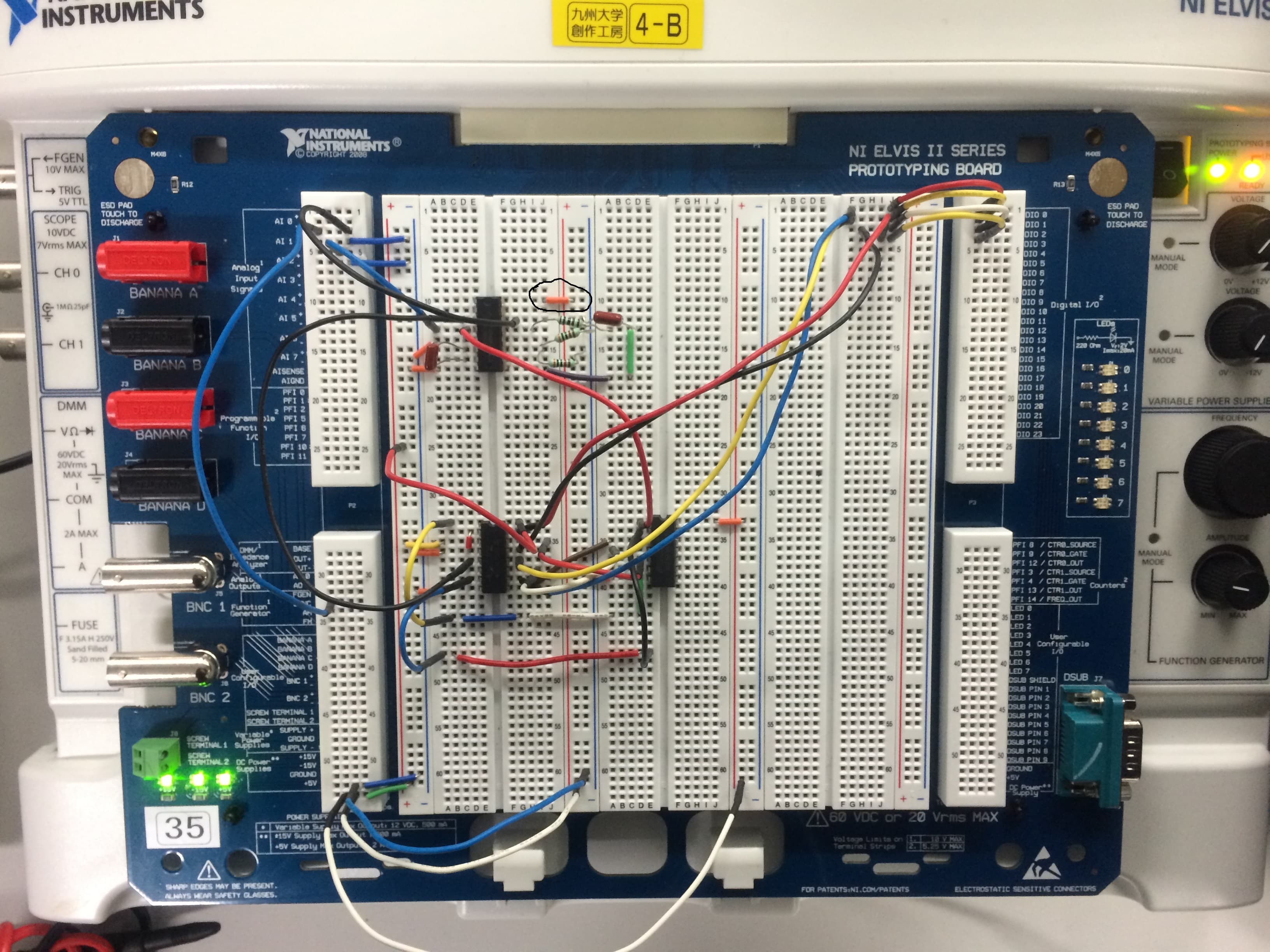
I have to build this PLL circuit and choose any 3 N (integer) of the N-divider. And then I have to observe the input signal Sig_in and the output signal VCO__out for each N. There are 2 schematics(see attached) that I used to build this circuit. The block diagram says 4MHz on one attachment, but 4kHz on the other. I decided to set the frequency to 4kHz because the waveform does not display a nice squarewave when the frequency is too high.
The frequency set on the function generator (FG) is the frequency reference, isn't it or is it not?
For each combination, the resulting frequency is different. So I suspect the problem is the values of the capacitors. There are two capacitors, here and I am not sure what to use. Anyway, I attached the results. I hope you can comment about them. I have to get a "frequency from ELVIS x (N+1)" frequency as a result.
Notice that the waves are locked when N=0 but not when N is not 0 :/ ?
The first three results are when 0.033 microF on pin 13, and 1nF on pin 6&7
The last three results are when 0.033 microF on pin 13, and 10nF on pin 6&7
I tested each circuit with three different N's.
Please explain to me what is the cause for my results and how to correct them!
YOU CAN ZOOM IN MY CIRCUIT TO SEE CLEARLY HOW I BUILT THIS CIRCUIT