Circuit to remotely control an electric switch

Guys,

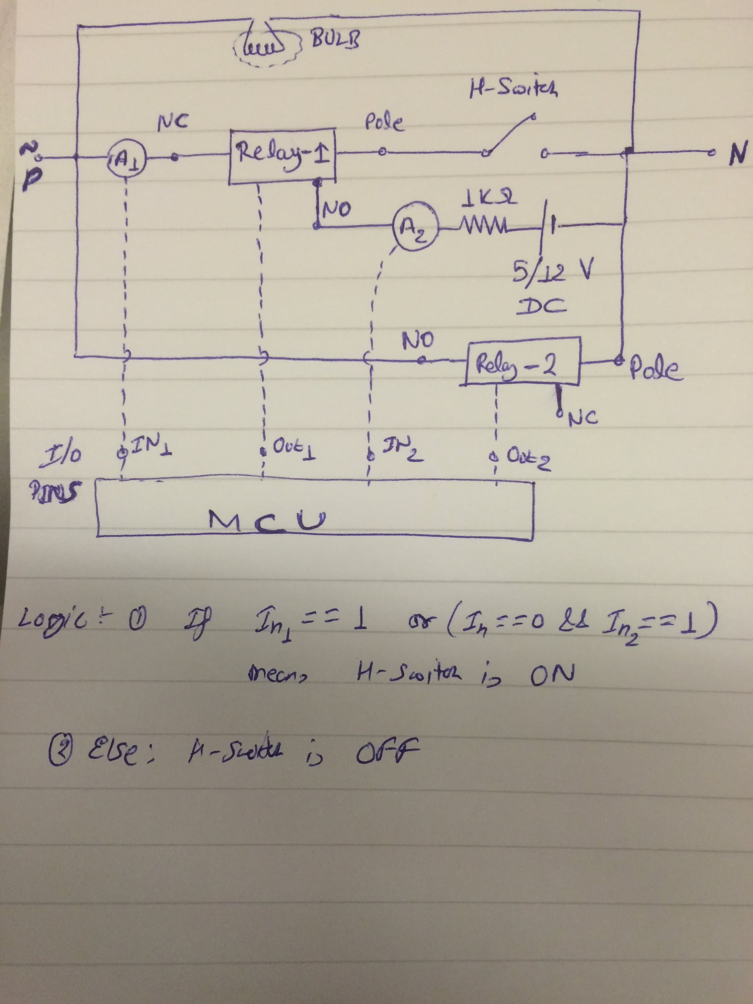
I have been trying to design an electric/electronic circuit to allow remote controlling of an electrical device (say, a bulb) in addition to its existing switch (electrical switch). A couple of issues:
1) I am finding it really difficult to synchronize between a) digital control (via a relay) and b) physical switch control.
2) I am using ACS 712 current sensor to detect if physical switch is switch on or off; so that MCU can take appropriate action (such as, if required, override physical switch on logic and turn the switch off). It's quite sensitive to change in temperature (if circuit left switched on for some time) and that results in a lot of noise in the output reading of ACS 712.

Attaching a snapshot of my circuit.

circuit

Any ideas to resolve this issue...or suggestion of a better circuit?

Replies

  • Ankita Katdare
    Ankita Katdare
    Tagging Mods #-Link-Snipped-# #-Link-Snipped-# #-Link-Snipped-#
  • Harshad Italiya
    Harshad Italiya
    #-Link-Snipped-# :
    From the detail what I understand is you are facing issues in sensing the physical switch as you are using current sensor in it. And the detail that you shared which says even temperature changes are making the noise and switch can malfunction so same thing can happen when you are turning Relay ON and OFF because of EMC/EMI you might get interference and that is giving you false signal.
    How if you use sense the mechanical switch by any other way? Like using Opto coupler to MCU?

    [​IMG]
  • lal
    lal
    It looks to me that circuit breaker will trip the very instant H-switch is switched On or Relay-2 is powered from the wiring diagram. I see a direct short between Phase and Neutral there.

    I was thinking, what if the voltage between H-switch terminals be monitored instead of current. Voltage is measured with high impedance devices which would cause negligible current flow and hence much less EMI.

    Potential difference across the switch will be zero when the switch or Relay 2 is ON. And it will be equal to supply voltage when both are off.

    The logic would then be,
    If Out2 = 0 and voltage between H-switch != 0
    Then H-switch is ON.

    Position of H-switch doesn't matter if Relay-2 is activated.
  • dsehrawat
    dsehrawat
    Thank you Guys...Appreciate that...I thought of using Voltage sensor at the very inception; but because of one basic flaw it was causing me issues; Positive voltage should be on the other side (away from bulb) of H-switch.
    Also, it was my bad...The bulb should be in series with this circuit (rather than in parallel).

    Thanks a ton for all the efforts...you are doing a gr8 job in handling this website venture.

You are reading an archived discussion.

Related Posts

Microsoft and Guide Dogs, a UK-based Charity for the blind and partially sighted, have collaborated to come up with an unique initiative called 'Cities Unlocked'. This project harnesses the new...
Sneakers have gotten quite a lot more expensive and high-tech in the last decade but their biggest makeover has happened very recently with ShiftWear. Yes, it’s an unheard brand as...
Why do computer science people get annoyed when someone asks: "Can you fix my computer?"
Tata Motors is all geared up for the launch of its newest hatchback - The Tata Zica - in January 2016 and the company has unveiled its first official images...
Hiii guys, Udan Media and Communications Pvt Ltd. Is ready to organize the fifth edition of MachAutoExpo-2016 a unique and most trustworthy Event to be held from 11th to 15th...