Difference Between Center Tap Full Wave Rectifier And Bridge Rectifier
The main difference in half wave and full wave rectifier is that the complete cycle is utilized in full wave rectifier. Alternate half cycle is inverted and thus a unidirectional current is achieved.
The full wave rectifier is further classified into two:
1. Center Tap Full Wave Rectifier
2. Bridge Rectifier
Let us discuss it one by one
Center Tap Full Wave Rectifier:
1. Here the AC input is applied through the transformer.
2. There are two diodes D1 and D2 connected to the opposite sides of the center tapped Secondary winding of the transformer. The anodes are connected to transformer winding while the cathode is connected to each other.
3. The load resistance RL is connected to the circuit.
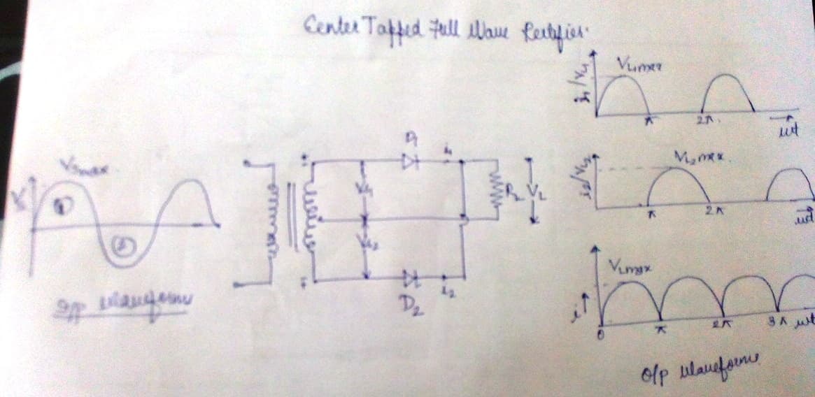
Operation of Center Tap Full Wave Rectifier:
1. When top of transformer is positive--------during first half cycle of the supply--------- Diode D1 positive----- D2 is Neagtive. Thus only D1 conducts .since it is forward biased. Thus current flows through the circuit, through RL and top of the secondary coil.
2. When bottom of the transformer is negative------- during the second half cycle------ Diode D@ positive--------D1 is negative---- Thus only D2 conducts as it is forward biased. The current flows throught he load resistance RL and bottom of the secondary making the cathode end of the load resistance RL positive.
3. Peak Inverse Voltage: This is the maximum possible voltage across the diode when it is reverse Biased.
PIV= (voltage across non conducting diode) + (voltage across load resistance RL )
PIV= 2VSMax
Bridge Rectifier
1. It consist of 4 diodes D1, D2, D3, D4 connected in the form of Wheatstone bridge network.
2. Two diagrammatically opposite junctions A and C are connected to the secondary of the transformer. And the other two B and D are connected to load RL.
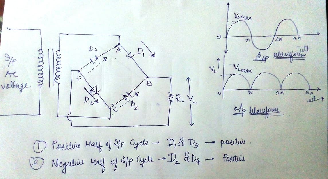
Operation of the Bridge Rectifier:
1. Top end of transformer positive---------first half of the cycle------D1 and D3 are positive means forward biased-----current flows through AB i.e. diode D1 ---- current enters at positive terminal of load and leaves at negative terminal ------ returns back through DC i.e. diode D3. During this time diode D2 and D4 are reversed biased and thus don’t conduct.
2. Bottom end of transformer positive---- second half of the cycle------ D2 and D4 are positive means forward biased----- Current flows through CB i.e. diode D2------current enters the load through positive terminal and leaves the negative terminal----- returns back through DA. During this time D1 and D3 are reversed biased.
3. Here the direction of current through RL remains the same during both the cycles.
4. PIV= VSMAX
The full wave rectifier is further classified into two:
1. Center Tap Full Wave Rectifier
2. Bridge Rectifier
Let us discuss it one by one
Center Tap Full Wave Rectifier:
1. Here the AC input is applied through the transformer.
2. There are two diodes D1 and D2 connected to the opposite sides of the center tapped Secondary winding of the transformer. The anodes are connected to transformer winding while the cathode is connected to each other.
3. The load resistance RL is connected to the circuit.
Operation of Center Tap Full Wave Rectifier:
1. When top of transformer is positive--------during first half cycle of the supply--------- Diode D1 positive----- D2 is Neagtive. Thus only D1 conducts .since it is forward biased. Thus current flows through the circuit, through RL and top of the secondary coil.
2. When bottom of the transformer is negative------- during the second half cycle------ Diode D@ positive--------D1 is negative---- Thus only D2 conducts as it is forward biased. The current flows throught he load resistance RL and bottom of the secondary making the cathode end of the load resistance RL positive.
3. Peak Inverse Voltage: This is the maximum possible voltage across the diode when it is reverse Biased.
PIV= (voltage across non conducting diode) + (voltage across load resistance RL )
PIV= 2VSMax
Bridge Rectifier
1. It consist of 4 diodes D1, D2, D3, D4 connected in the form of Wheatstone bridge network.
2. Two diagrammatically opposite junctions A and C are connected to the secondary of the transformer. And the other two B and D are connected to load RL.
Operation of the Bridge Rectifier:
1. Top end of transformer positive---------first half of the cycle------D1 and D3 are positive means forward biased-----current flows through AB i.e. diode D1 ---- current enters at positive terminal of load and leaves at negative terminal ------ returns back through DC i.e. diode D3. During this time diode D2 and D4 are reversed biased and thus don’t conduct.
2. Bottom end of transformer positive---- second half of the cycle------ D2 and D4 are positive means forward biased----- Current flows through CB i.e. diode D2------current enters the load through positive terminal and leaves the negative terminal----- returns back through DA. During this time D1 and D3 are reversed biased.
3. Here the direction of current through RL remains the same during both the cycles.
4. PIV= VSMAX
0
