CrazyEngineers
  • Need help- 3 Phase Inverter

    Updated: Oct 26, 2024
    Views: 1.2K
    3-phase_inverter_cjc

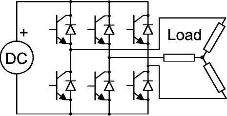
    6 IGBTs are used as a switch.
    How input pulses should be given to generate 3 phase a.c. inverter.(120 degree phase different).

    any link welcomed.
    Thank you
    0
    Replies
Howdy guest!
Dear guest, you must be logged-in to participate on CrazyEngineers. We would love to have you as a member of our community. Consider creating an account or login.
Replies
  • Nishant Patel

    MemberFeb 26, 2013

    <a href="https://www.google.co.in/search?hl=en&q=3+phase+inverter&bav=on.2,or.r_gc.r_pw.r_qf.&bvm=bv.42965579,d.bmk&biw=1280&bih=675&um=1&ie=UTF-8&tbm=isch&source=og&sa=N&tab=wi&ei=OZEtUZzsNoO3rAf6wIHQBA#imgrc=GULXzZmg_X2rUM%3A%3BvjcQSfYqNCNtdM%3Bhttp%253A%252F%252Ftechno-fandom.org%252F~hobbit%252Fcars%252Ftraining%252F800%252Fm111.jpg%3Bhttp%253A%252F%252Ftechno-fandom.org%252F~hobbit%252Fcars%252Ftraining%252Fm101.html%3B800%3B600" target="_blank" rel="nofollow noopener noreferrer">3 phase inverter - Google Search</a>

    Consider this circuit.
    Are you sure? This action cannot be undone.
    Cancel
  • Jeffrey Arulraj

    MemberFeb 27, 2013

    As I find a DC supply has to used and also use

    Vdc=Vac/(2)^1/2

    And so for Vac we get Vdc to be about sqroot(2) times more than the desired op

    If you need 230 V AC use Sqrt(2)*230V DC supply
    Are you sure? This action cannot be undone.
    Cancel
  • Nishant Patel

    MemberFeb 27, 2013

    Thanks to inform...but question is,
    how the pulses to be given to the 6 igbts shown in figure so that we can convert to 3 phase signal.
    Are you sure? This action cannot be undone.
    Cancel
  • Jeffrey Arulraj

    MemberFeb 27, 2013

    Nishant Patel
    Thanks to inform...but question is,
    how the pulses to be given to the 6 igbts shown in figure so that we can convert to 3 phase signal.
    Why do you need to worry about that Just give DC supply to the IGBT's as per the circuit diagram No need for any pulses and all
    Are you sure? This action cannot be undone.
    Cancel
  • Kaustubh Katdare

    AdministratorFeb 27, 2013

    #-Link-Snipped-# : Please use the file upload facility so that images appear within the posts 😀
    Are you sure? This action cannot be undone.
    Cancel
  • lal

    MemberFeb 27, 2013

    #-Link-Snipped-#, he is mentioning about the firing pulses. Well, it matters!

    #-Link-Snipped-#
    There are two modes of operation 180 degrees mod and 120 degrees mode. In each of these modes, the time period for which the IGBTs has to be in ON state are different. In 180 degree conduction mode, each semiconductor switch will conduct for 180 degrees (that is 10ms for 50Hz) and at any moment three IGBTs will be in ON state. In 120 degrees mode, one IGBT will be conducting for 120 degrees and at any moment two switches will be in ON state.

    Let me try to number those IGBTs in the figure. The top IGBT in the first leg be numbered '1'. The bottom one in 3rd leg is '2', 2nd leg top one is '3', 1st leg bottom one '4', 3rd leg top one '5' and 2nd leg bottom one '6'. Oops! 😐 Hope its clear.

    Here goes the firing sequence. In 180 degrees mode, each IGBT has to be kept ON for 180 degrees. IGBTs are switched on sequentially at every 60 degrees. Let switch 1 (s1) be fired at 0 degree. Then at 60 degrees fire S2; again after another 60 degrees fire S3. After another 60 degrees s1 is switched OFF (it completes 180 degrees conduction by this time) and s4 is turned on. This cycle continues.

    In 120 degrees conduction mode, the very same thing happens except that each IGBT is turned ON only for 120 degrees. By the way, these are purely theoretical. In practise, the actual timing of switching ON and OFF of the switches will be a bit different. Other factors in the circuit are also considered when deciding the actual firing pulse width.

    I made it a bit too much complicated I guess 😐
    Are you sure? This action cannot be undone.
    Cancel
  • Jeffrey Arulraj

    MemberFeb 27, 2013

    Thanks #-Link-Snipped-# for opening my eyes I didn't think this way
    Are you sure? This action cannot be undone.
    Cancel
  • Nishant Patel

    MemberFeb 27, 2013

    #-Link-Snipped-# ..thanks a lot for making it clear..
    #-Link-Snipped-# 😀
    #-Link-Snipped-# yes sir..😀
    Are you sure? This action cannot be undone.
    Cancel
  • arunchary

    MemberFeb 28, 2013

    @#-Link-Snipped-#
    its good to understood,but if it comes to implementation on softwares it may get variations. if it is matlab,then it is easy to sort out because the option to get triggering of IGBT is possible using pulse generator,..but in other platforms it may be happens but good for going lal's concept in matlab is pretty good..
    Are you sure? This action cannot be undone.
    Cancel
  • lal

    MemberFeb 28, 2013

    Whichever software you use or whichever trigger you use or whichever pulse generator you use, the order in which IGBTs are triggerd has to be right. And the pulse widths define the frequency of output!
    Are you sure? This action cannot be undone.
    Cancel
  • arunchary

    MemberMar 1, 2013

    yes exactly lal its depends on pulsewidths to trigger the gate..
    Are you sure? This action cannot be undone.
    Cancel
Home Channels Search Login Register