DIY water level cum pump controller
the circuit diagram explains all. the sensors are placed in well , and in overhead tank. if the condition, i.e the water level in well is high, the water level in the tank is very low, the voltage is in the desired range. if all of these conditions satisfy then the pump will turn on. its very simple and can be used as a beginner level project in embedded system. i have done it years back, and happy to let all of CEANs to tackle it. it also checks for any impurities in water (by testing the conductivity of water)
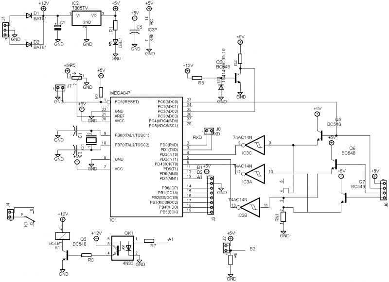
circuit diagram:
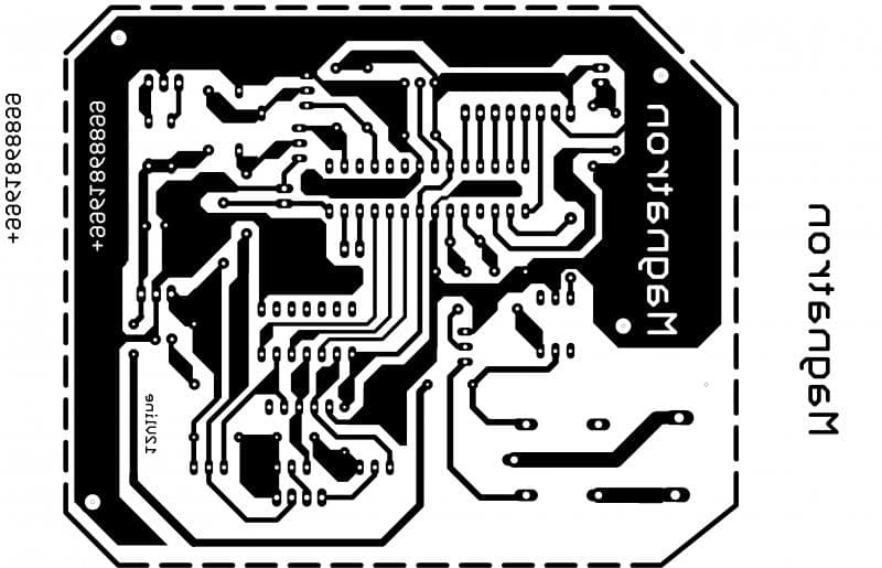
pcb layout:
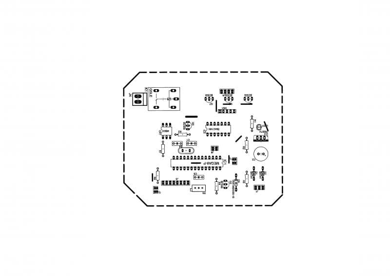
top silkscreen:
program (with hex code):
#-Link-Snipped-#
circuit diagram:
pcb layout:
top silkscreen:
program (with hex code):
#-Link-Snipped-#
0