De-Dusting Aspiration System Design Calculations Required - Layout attached

Hello Everyone!

I would like to have some help and support from you guys in calculating a few parameters regarding centrifugal fan in aspiration system. Your help will be highly appreciated. Thanks in advance.

Aspiration System for Flour Mills

Please check the attached pic for an overview of the system.

2mxiik9

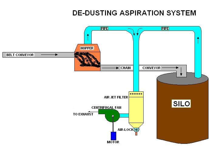
A belt conveyor carrys the raw material (Wheat) and transfers it to a chain conveyor via a hopper at 750 MT/hr (Metric Tonnes per hour). The chain conveyor then transfers the material to a silo for storage. When the material falls from the belt conveyor to the chain conveyor and chain conveyor to the silo, dust is generated. These are grain dust and have to be removed (aspirated).

So an aspiration system, consisting of a centrifugal fan via a filter is used to evacuate the dust + air. Now am facing a problem with the fan and need to change it. But I don't have all the details because the manuals of these machines are not available to find the specs and even the name plate has worn out.

The only details that I've are as follows:

Motor Speed, N = 2850 rpm
Motor Power Rating = 7.5 KW

Filter = 36 sleeves with 15.5 cm dia and 240 cm height

Centrifugal fan dia (measured from outside) = 37 cm

I want to calculate how much capacity of a fan is required to remove the grain dust having adensity of 150 kg/cu.m from the hopper and the top entrance of the silo via PVC pipe. I have the dimensions of the hopper, filter and pipe but the friction losses need to be calculated for a total volume to find the velocity first.

I want to calculate the following parameters:

Total Pressure,
Air velocity
Disharge,Q in cu.m/hr

Awaiting your support ๐Ÿ˜€

Replies

  • Kaustubh Katdare
    Kaustubh Katdare
    Don't worry, I've updated your post with the new picture. ๐Ÿ‘
  • AbdulRahman.Mech
    AbdulRahman.Mech
    Thanks Big K ๐Ÿ˜€ still waiting for help โ˜• hope someone initiates the discussion soon...
  • Ramani Aswath
    Ramani Aswath
    More details needed. Length and size of ducts, number of bends. filter pressure drop in half choked condition and such.
    Usually a backward swept bladed fan of 7.5 KW power will have an air flow of about 16000 cu.mtrs/Hr at 100 mm SWG pressure and about 4000 cu.mtrs/Hr at 200 mm SWG.
    There are many manufacturers for this.
  • AbdulRahman.Mech
    AbdulRahman.Mech
    Mr. Ramani thanks for your attention to my thread.
    The existing PVC pipe diameter connecting from the bin to the fan via filter is 14" with a total length of 110 meters with 15 90 degree standard bends. This 14" is the main pipe line for suction.
    The PVC pipe connecting the silo to the 14" main pipe is 12" in dia at a total length of 15m with 10 90degree bends..
    Please ignore the previously mentioned dia of fan as 37cm. The backward centrifugal fan's actual dia is 52cm.
    Industrial Air changes/minute = 7

    Now I would like to calculate the flow rate generated by this fan and the the total pressure.

    For the discharge, Q = AV
    we've the area = 0.09663 m (for 14" pipe)
    but I don't have either Q or V to calculate any one of the parameters from the above formula.

    My objective is to find the actual flow rate, pressure generated by the fan and velocity.

    Thanks for your support. Looking forward for further discussion Sir.
  • AbdulRahman.Mech
    AbdulRahman.Mech
    Mr. Big K. I just posted new details and deleted by mistake. can you please re-post it again?
  • Ramani Aswath
    Ramani Aswath
    The system is difficult to analyse. The same fan is serving two branches. There is a 14" main line with a 12" offtake somewhere in between.
    The pressure drop is directly proportional to the square of the flow rate.
    The fan flow is decided by the pressure drop. The head loss in the duct is decided by the duct design including fittings. It is not possible to calculate analytically all parameters.

    What can be attempted is to do trial and error iterations assuming a 7.5 KW fan.
    The added complication in this system is the parallel 12" branch. This is analogous to an electrical circuit which has a series parallel connection. The suction pressure where the 12" pipe joins the 14" pipe cannot be found without knowing the exact dimensions of the duct layout including the bends.

    This kind of detailed engineering is not possible on a forum like this. At best we can give some pointers on what has to be done. You may have to handle the rest suitably.

    Basis: Fan capacity 4000 cubic meters/hr @ 200 mm SWG pressure drop and 16000 cubic meters/hr @ 100 mm SWG pressure drop for a 7.5 KW fan.
    The 12" line takes off 1/4 way of 14" line from hopper end.

    Flow in 14" pipe at hopper end = 2300 cu.ft./min (Corresponding to 4000 cu.mtr./hr)
    Flow in 12" pipe = 1150 cu.ft./min (Corresponding to 2000 cu.mtr./hr)

    Calculations
    Eqivalent length of 14" pipe = 720 feet including 15 bends.
    Eqivalent length of 12" pipe = 250 feet including 10 bends.
    (#-Link-Snipped-#)

    Total pressure drop for above configuration of duct and flow = 165mm SWG
    (Air Ducts - Major Friction Head Loss, Online Calculator)

    This leaves 200 - 165 = 35 mm SWG for the filter.

    The 7.5 KW fan can handle this.
  • AbdulRahman.Mech
    AbdulRahman.Mech
    Thanks for the heads up Mr. Ramani. Points well noted. Will contact you if in case I come across any difficulties.
  • venkatarao15579
    venkatarao15579
    Dear sir have read all the interactions , and i think its a right place to put my querry.
    I want a blower system for a bin/Silo.The purpose of the fan is to remove light dust particles of sp density within 1.5 gm/cc (max size 63 micron) from the bin when material is fed through conveyor.
    My concern is that the
    1) volume of material in silo is not consistant.
    2)possibility of heavier particles(product) being sucked to the fan
    3)The dust has to be sent to bag filter , hence there will be considerable head loss in the ducting to bag filter.
    Help me with the basics of this engineering.
    The bin bottom portion is conical for 25% volume and rest is cylindrical.
    Please help me with an approch to design suitable de dusting fan.
  • Ramani Aswath
    Ramani Aswath
    What is the product? Have you considered the option of de-dusting the product before it leaves the conveyor? Then you can leave the bin as it is without having to do extensive (and expensive) alterations to it. You can easily introduce a centrifugal separator in the suction line to separate and return any heavier product particles that may incidentally get sucked.

You are reading an archived discussion.

Related Posts

Flipkar is offering some of selected albums from all geners to download MP3 for fee.๐Ÿ˜ Get here a legal copy of yours. This is amazing offer and some of the...
How to apply input:230V,1phase AC to a transformer in proteus simulation?
someone can give me some ideas for my thermodynamics project? i tried to do an air conditioner and a stirling motor, but the teacher refused these two projects. now i...
So my title says it all ....I wanna know why creat() command in C lacks "e" ? I wonder why Ken Thompson kept creat() instead of create() ? Anyone got...
I'm going to enter my 4th year. I'm interested in doing a project in Automotive Engineering, but i'm not sure which one would be possible to attempt at such an...