Application specific problems: DC voltage comparator circuit
@princetan-P76mmI
•
Oct 26, 2024
Oct 26, 2024
1.9K
Hi fellow CEians,
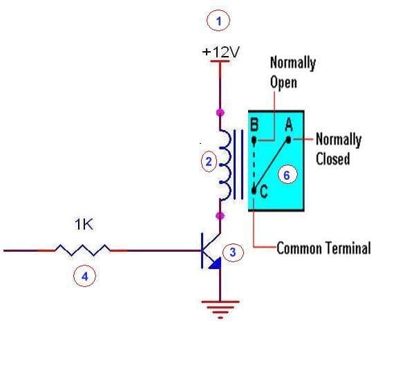
I have a project currently requiring to compare a voltage to 24V reference and it must trigger a relay output when the input voltage is lower than 24V reference. Both voltages are DC supply. I planned to use LM393 and provide it with the same 24V reference as supply. Can it be done? Does the parameter of input common mode voltage range affect my application? I'm guessing it does, meaning I need to use a voltage divider to drop both input and reference voltage to below 24V? Any help is appreciated.
Regards,
Prince.