Analysis of Florida International University pedestrian bridge collapse
<a href="https://en.wikipedia.org/wiki/Florida_International_University_pedestrian_bridge_collapse" target="_blank" rel="nofollow noopener noreferrer">Florida International University Pedestrian Bridge Collapse</a>
The Florida Department of Transport has released the engineering design and construction plans for the FIU pedestrian bridge, which can be downloaded from this link.
#-Link-Snipped-#
My analysis of these engineer's plans have revealed that my earlier suspicion that truss member 11 was dangerously weak has been confirmed, to such a degree that the failure of member 11 (and consequently the collapse of whole bridge) was to be expected as a result of damage sustained to member 11 under the total compression load experienced after the bridge was placed on the piers but before the planned destressing of the Post-Tensioning (P.T.) Bars.
The engineering plans, signed off by the "Engineer of Record", W. Denney Pate of FIGG, were at dangerously at fault and so the construction team by simply following the plans faithfully would have guaranteed the collapse of the bridge.
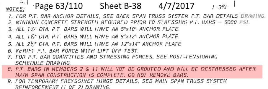
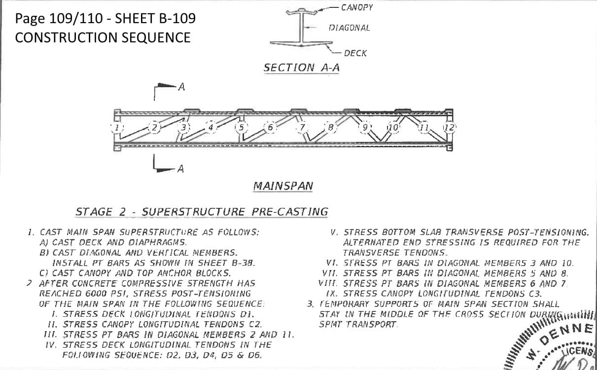
The first point of concern to note from the engineering plans is that the plan's P.T. bar tensioning begins once the concrete reaches a strength of only 6,000 psi or more, as this quote shows -
6,000 psi is less than the final full strength of the concrete was expected to be (at least 8,500 psi) when it has fully set and in this case proceeding with the construction while the concrete was not fully hard was a contributing factor to the collapse.
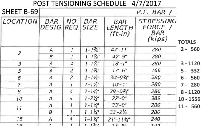
The next point of concern to note is that the engineer's plans recommend a P.T. bar setting for the 2 P.T. bars in member 11 which together total a P.T. bar tension of 560 KIP.

The results of my truss calculations show that the dead weight of the bridge exerts on member 11
* a tension force of 304 KIP while the bridge is being transported and
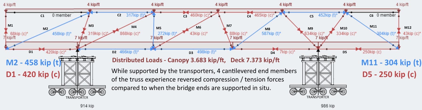
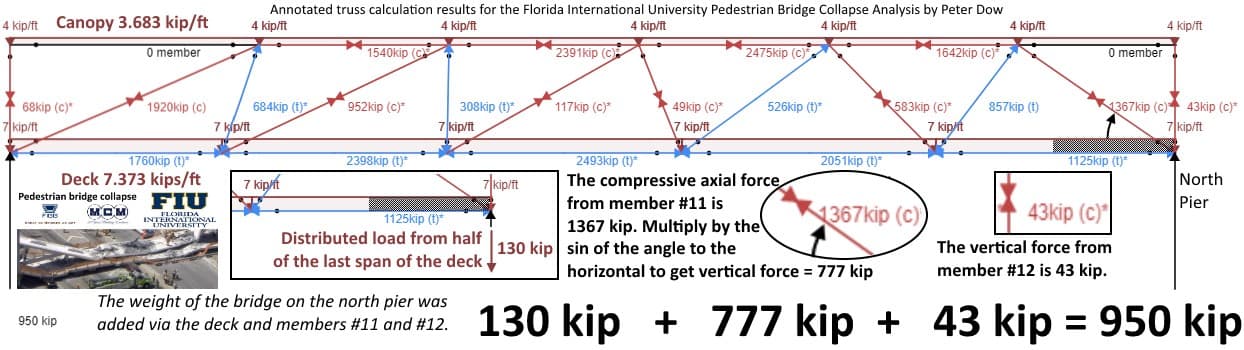
* a compression force of 1367 KIP when the bridge is placed on the piers, which is a point of concern to note
The P.T. bar tension of 560 KIP on member 11 is somewhat higher than it needs to be - I have suggested that a P.T. bar tension of 390 KIP would have been plenty.

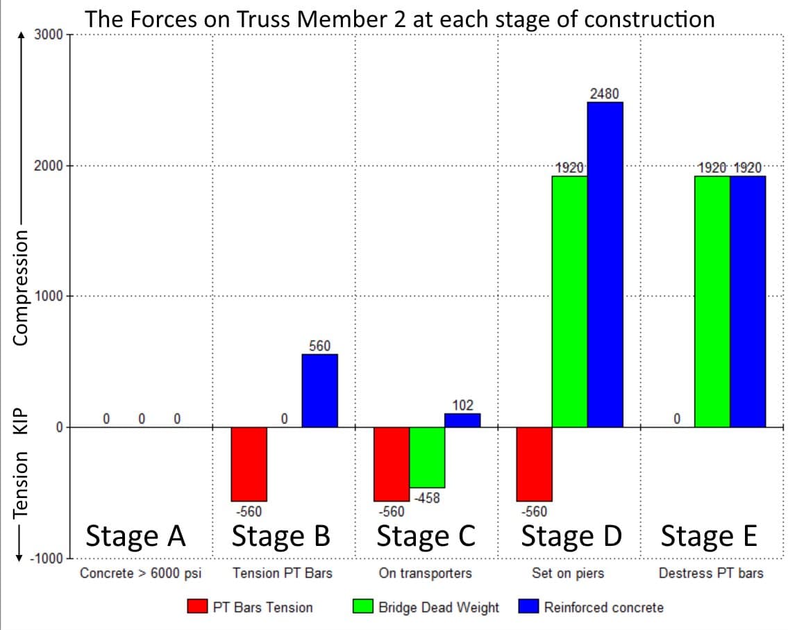
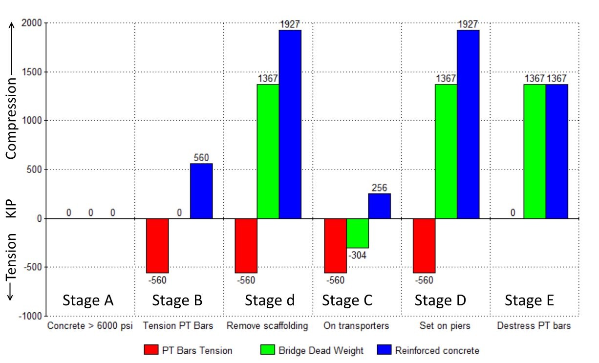
Now let us consider what all those forces together in the sequence they were applied mean for the compression force on the reinforced concrete of member 11.
I have considered 5 different stages, which I have named "A, B, C, D and E".
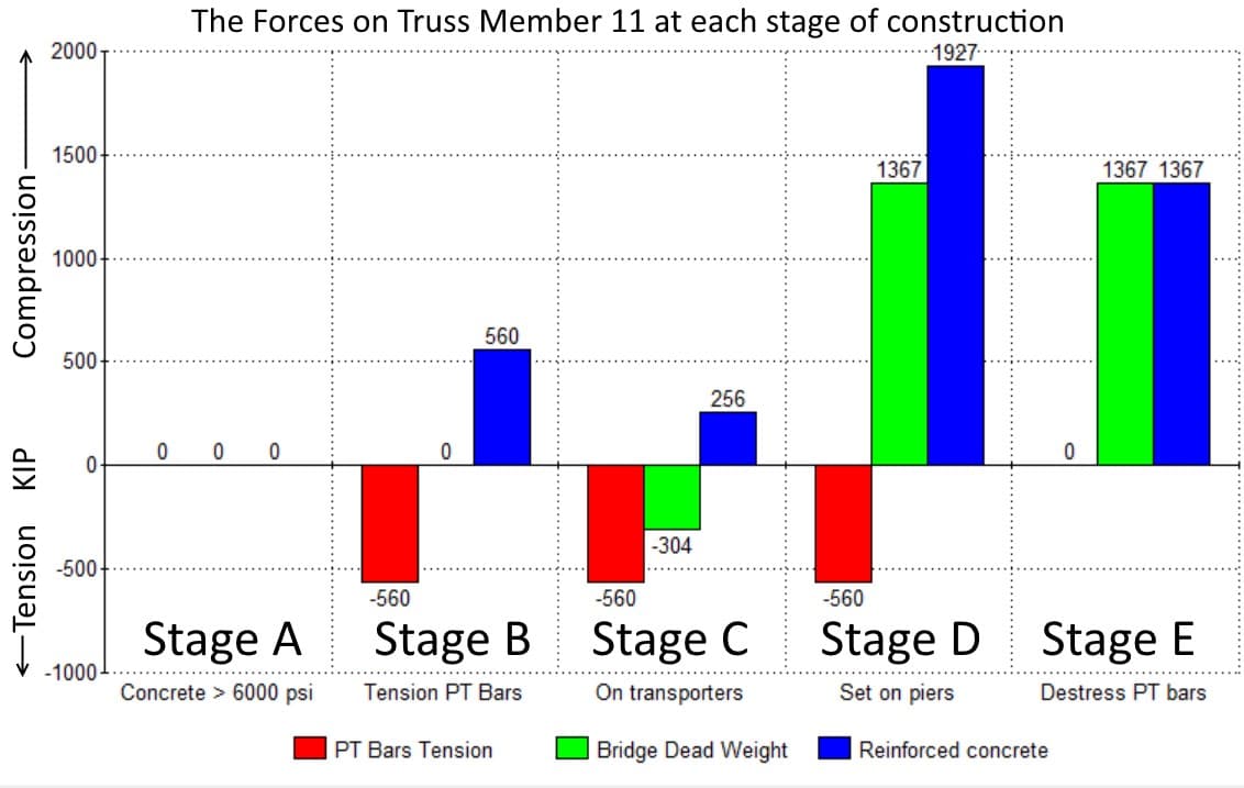
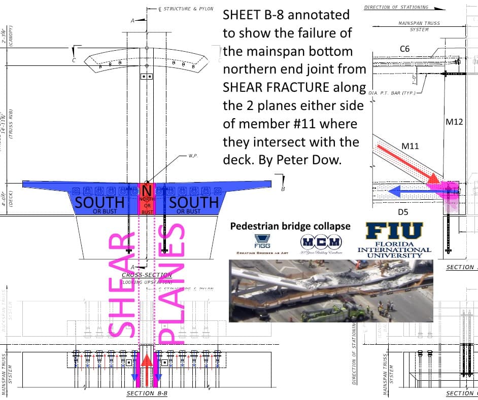
The bridge collapsed as a result of critical damage to the concrete member 11 sustained in stage D, when the compression force on the reinforced concrete of member 11 was at a maximum, though it appears that member 11 survived long enough for the destressing procedure of the P.T. bars of member 11 to begin.
However, the bridge never got to stage E in good order, sadly, but inevitably because of following the fatally flawed engineering plans.
Stage A
The concrete has hardened to at least 6,000 PSI and so post-tensioning is about to begin but at this stage the mainspan is still resting on the ground, so there are no troublesome forces on member 11, no P.T. bar tension, no bridge dead weight and so the reinforced concrete is not being compressed very much at all except under its own weight and that of the canopy immediately above it, but we will ignore that for now.
Stage B
The P.T. bars of member 11 have been tensioned to the recommended amount - a total of 560 KIP and that tension force on the P.T. bars is being provided by an equal and opposite compressive force of 560 KIP on the reinforced concrete. But the mainspan is still on the ground so not much in the way of dead weight of the bridge to worry about yet.
Stage C
The mainspan has been lifted onto the transporters and now the dead weight of the bridge is exerting an external tension force of 304 KIP on member 11. This has the effect of reducing the compressive force on the reinforced concrete of member 11 by 304 KIP down to 256 KIP.
Stage D
In this case, "D" for danger and for "Doom".
This is when things take a turn for the worse. The bridge gets placed on the piers and now the dead weight of the bridge is applying a compression force of 1367 KIP on to member 11.
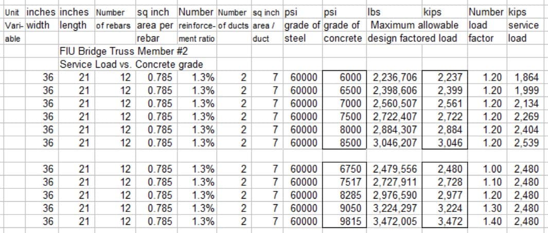
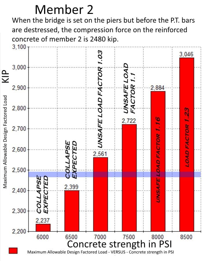
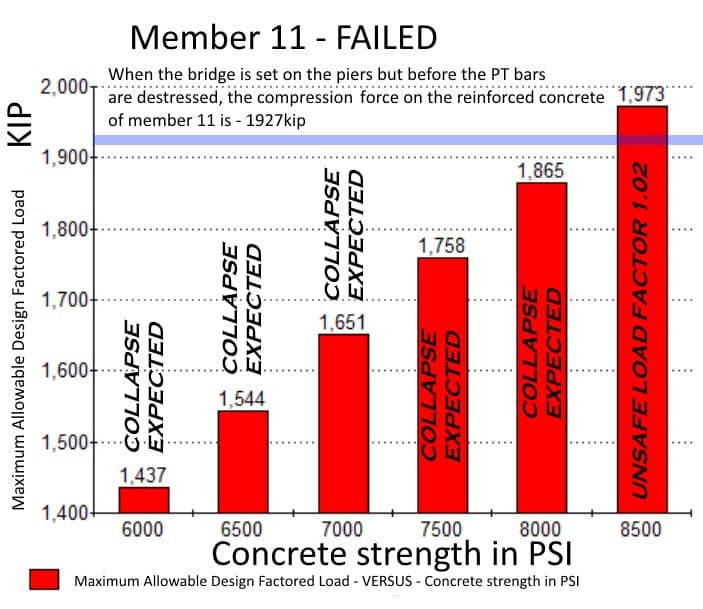
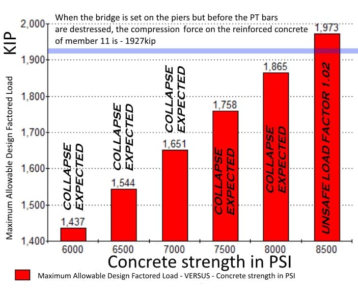
So now the reinforced concrete has to take the full compression force of 560 KIP from the P.T. bars under tension plus the 1367 KIP dead weight of the bridge to suffer a total of 1927 KIP of compression force, which is more than member 11 is able to cope with, especially so if the concrete has not reached is full strength of at least 8500 PSI, as is shown in this table from my concrete column calculator and this bar chart.
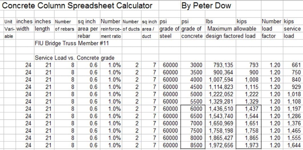
Therefore damage to and eventual failure of member 11 - and the collapse of the bridge - must be expected if the strength of the concrete was only 8,000 psi or less and the plans only require that the strength of the concrete at this stage be at least "6,000 psi".
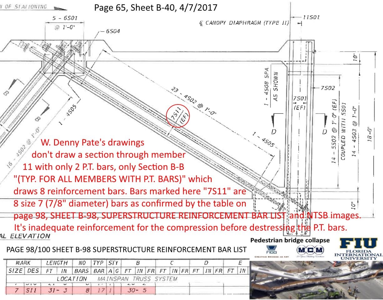
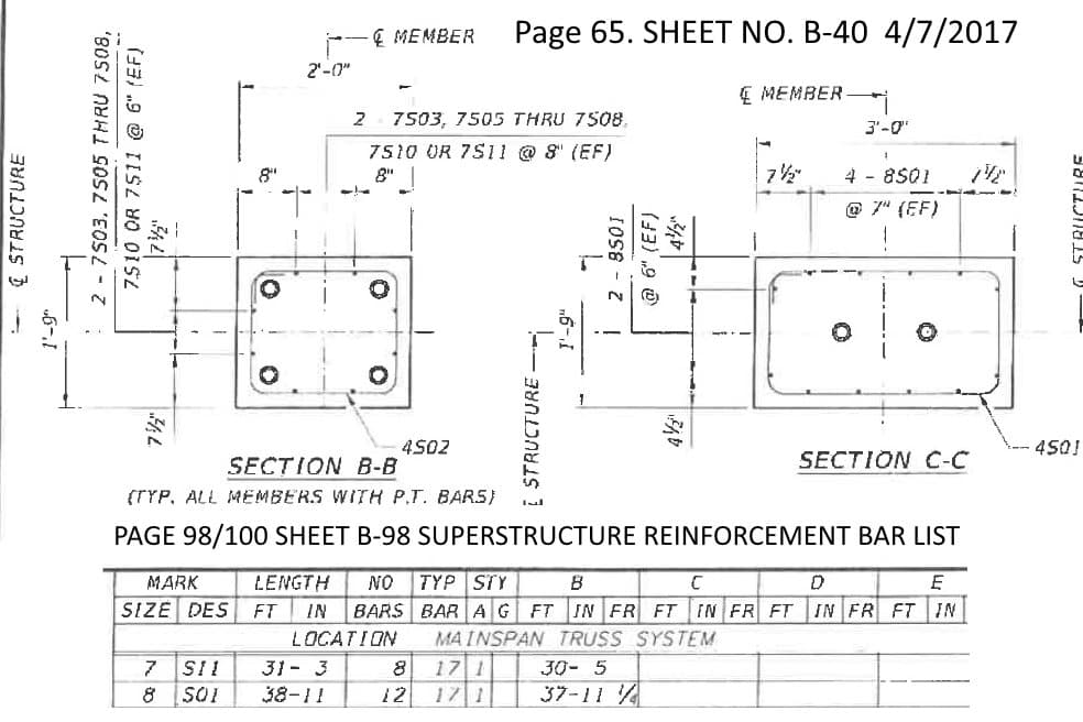
A point of concern to note is that the plans only call for 8 number 7 (diameter 7/8" inch, area 0.6 square inches each, axially orientated reinforcing bars), just barely 1% of a reinforcement ratio for that size of concrete member. The compression strength of member 11 was from 99% concrete by areal cross-section, only 1% reinforcing bars.
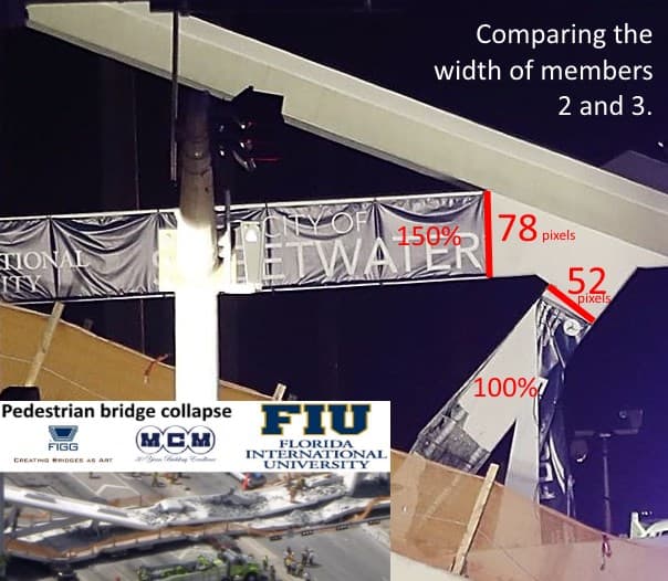
Another point of concern to note is that plans only call for member 11 to be of size 24 inches by 21 inches in cross section. Whereas the equivalent member at the south side of the bridge, member 2 was 150% wider, 36 inches by 21 inches and although it was carrying a higher dead weight from the bridge, member 2 survived intact.
Member 11 was not thick enough, it wasn't reinforced with steel bar enough, it was not strong enough to survive undamaged the forces it was subjected to during stage D.
The P.T. bars, 1.75" diameter steel bars, didn't contribute to the long term compression strength of member 11, but actually contributed to ruining the long term compression strength in stage D.
(Continues in a subsequent post)
The Florida Department of Transport has released the engineering design and construction plans for the FIU pedestrian bridge, which can be downloaded from this link.
#-Link-Snipped-#
My analysis of these engineer's plans have revealed that my earlier suspicion that truss member 11 was dangerously weak has been confirmed, to such a degree that the failure of member 11 (and consequently the collapse of whole bridge) was to be expected as a result of damage sustained to member 11 under the total compression load experienced after the bridge was placed on the piers but before the planned destressing of the Post-Tensioning (P.T.) Bars.
The engineering plans, signed off by the "Engineer of Record", W. Denney Pate of FIGG, were at dangerously at fault and so the construction team by simply following the plans faithfully would have guaranteed the collapse of the bridge.
The first point of concern to note from the engineering plans is that the plan's P.T. bar tensioning begins once the concrete reaches a strength of only 6,000 psi or more, as this quote shows -
"CONSTRUCTION SEQUENCE - STAGE 2 - SUPERSTRUCTURE PRE-CASTING
2. AFTER CONCRETE COMPRESSIVE STRENGTH HAS REACHED 6000 PSI, STRESS POST-TENSIONING OF THE MAIN SPAN IN THE FOLLOWING SEQUENCE ..."
2. AFTER CONCRETE COMPRESSIVE STRENGTH HAS REACHED 6000 PSI, STRESS POST-TENSIONING OF THE MAIN SPAN IN THE FOLLOWING SEQUENCE ..."
6,000 psi is less than the final full strength of the concrete was expected to be (at least 8,500 psi) when it has fully set and in this case proceeding with the construction while the concrete was not fully hard was a contributing factor to the collapse.
The next point of concern to note is that the engineer's plans recommend a P.T. bar setting for the 2 P.T. bars in member 11 which together total a P.T. bar tension of 560 KIP.
The results of my truss calculations show that the dead weight of the bridge exerts on member 11
* a tension force of 304 KIP while the bridge is being transported and
* a compression force of 1367 KIP when the bridge is placed on the piers, which is a point of concern to note
The P.T. bar tension of 560 KIP on member 11 is somewhat higher than it needs to be - I have suggested that a P.T. bar tension of 390 KIP would have been plenty.
Now let us consider what all those forces together in the sequence they were applied mean for the compression force on the reinforced concrete of member 11.
I have considered 5 different stages, which I have named "A, B, C, D and E".
The bridge collapsed as a result of critical damage to the concrete member 11 sustained in stage D, when the compression force on the reinforced concrete of member 11 was at a maximum, though it appears that member 11 survived long enough for the destressing procedure of the P.T. bars of member 11 to begin.
However, the bridge never got to stage E in good order, sadly, but inevitably because of following the fatally flawed engineering plans.
Stage A
The concrete has hardened to at least 6,000 PSI and so post-tensioning is about to begin but at this stage the mainspan is still resting on the ground, so there are no troublesome forces on member 11, no P.T. bar tension, no bridge dead weight and so the reinforced concrete is not being compressed very much at all except under its own weight and that of the canopy immediately above it, but we will ignore that for now.
Stage B
The P.T. bars of member 11 have been tensioned to the recommended amount - a total of 560 KIP and that tension force on the P.T. bars is being provided by an equal and opposite compressive force of 560 KIP on the reinforced concrete. But the mainspan is still on the ground so not much in the way of dead weight of the bridge to worry about yet.
Stage C
The mainspan has been lifted onto the transporters and now the dead weight of the bridge is exerting an external tension force of 304 KIP on member 11. This has the effect of reducing the compressive force on the reinforced concrete of member 11 by 304 KIP down to 256 KIP.
Stage D
In this case, "D" for danger and for "Doom".
This is when things take a turn for the worse. The bridge gets placed on the piers and now the dead weight of the bridge is applying a compression force of 1367 KIP on to member 11.
So now the reinforced concrete has to take the full compression force of 560 KIP from the P.T. bars under tension plus the 1367 KIP dead weight of the bridge to suffer a total of 1927 KIP of compression force, which is more than member 11 is able to cope with, especially so if the concrete has not reached is full strength of at least 8500 PSI, as is shown in this table from my concrete column calculator and this bar chart.
Therefore damage to and eventual failure of member 11 - and the collapse of the bridge - must be expected if the strength of the concrete was only 8,000 psi or less and the plans only require that the strength of the concrete at this stage be at least "6,000 psi".
A point of concern to note is that the plans only call for 8 number 7 (diameter 7/8" inch, area 0.6 square inches each, axially orientated reinforcing bars), just barely 1% of a reinforcement ratio for that size of concrete member. The compression strength of member 11 was from 99% concrete by areal cross-section, only 1% reinforcing bars.
Another point of concern to note is that plans only call for member 11 to be of size 24 inches by 21 inches in cross section. Whereas the equivalent member at the south side of the bridge, member 2 was 150% wider, 36 inches by 21 inches and although it was carrying a higher dead weight from the bridge, member 2 survived intact.
Member 11 was not thick enough, it wasn't reinforced with steel bar enough, it was not strong enough to survive undamaged the forces it was subjected to during stage D.
The P.T. bars, 1.75" diameter steel bars, didn't contribute to the long term compression strength of member 11, but actually contributed to ruining the long term compression strength in stage D.
(Continues in a subsequent post)
0