
Optimizing the design of a magnetic circuit actuator
The aim is to optimize this actuator to get the maximum force from it. Here is the circuit diagram below:
#-Link-Snipped-#
#-Link-Snipped-#
Length of air gap top (Ragt in diagram) = 0.5 mm
Length of air gap centre (Ragc) = 0.25 mm
Current in coil = 0.8 A (I calculated it), current in coil must be less than 1A
I'm not gonna put too many calculations here because it might be too long and people reading it will get a headache, but anyway I have some questions
Will the flux divide equally ?, my guess is no because the air gap reluctance's are different
To get the drop in RcoreBCDA, I use F = Hl, now my question is will the mean path length(l) run from ABCD ?
Lastly, any guidelines on how to solve for the magnetic fluxes and mmf drops ?, I did attempt it but not sure it it's correct
Any help will be greatly appreciated, this my design project and it's due very soon
#-Link-Snipped-#
#-Link-Snipped-#
Length of air gap top (Ragt in diagram) = 0.5 mm
Length of air gap centre (Ragc) = 0.25 mm
Current in coil = 0.8 A (I calculated it), current in coil must be less than 1A
I'm not gonna put too many calculations here because it might be too long and people reading it will get a headache, but anyway I have some questions
Will the flux divide equally ?, my guess is no because the air gap reluctance's are different
To get the drop in RcoreBCDA, I use F = Hl, now my question is will the mean path length(l) run from ABCD ?
Lastly, any guidelines on how to solve for the magnetic fluxes and mmf drops ?, I did attempt it but not sure it it's correct
Any help will be greatly appreciated, this my design project and it's due very soon
Replies
-
 lalDefinitely the flux will not be divided equally between the limbs, due to non uniform reluctance in the paths.
But, I assume by carefully designing the core, a satisfactory result could be achieved. By increasing the cross sectional area of top limb, RcoreBCDA could be reduced, thus allowing more magnetic flux to flow through that limb. Further, a thinner bottom limb would increase its reluctance.
I am not quite sure how well that would turn out to be. Yet, let's try to work a way out. -
Agar
Thanks for replying, ok let me explain a bit more in detail. The lamination's are of constant thickness of 0.5 mm and the maximum thickness of the core is 16 mmlalDefinitely the flux will not be divided equally between the limbs, due to non uniform reluctance in the paths.
But, I assume by carefully designing the core, a satisfactory result could be achieved. By increasing the cross sectional area of top limb, RcoreBCDA could be reduced, thus allowing more magnetic flux to flow through that limb. Further, a thinner bottom limb would increase its reluctance.
I am not quite sure how well that would turn out to be. Yet, let's try to work a way out.
These are the constraints:
12V dc input supply
Current not to exceed 1A in the coil
Maximum depth of core is 16 mm
Lamination type, hot rolled silicon steel
Parameters under my control:
Number of turns on coil
Area of the core
Top air gap width
The objective is to get the highest force/weight ratio
Here's the dimensions:
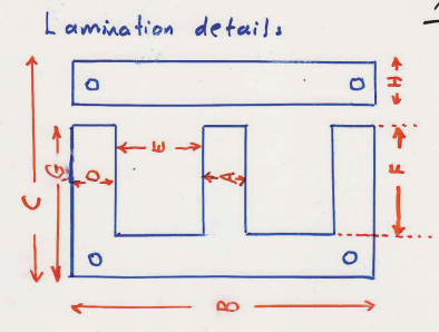
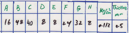
All dimensions are in mm. The 0.5mm is the thickness per lamination.
I will show some of my work here what iv'e done so far:
The first thing is to calculate the current in the coil:
Using, R = p*length of wire/Area of wire , p = resistivity of copper wire
Length wire = Number of turns*Perimeter of bobbin , Perimeter of bobbin = 74mm
Area of wire = (pi*d^2)/4, where d is diameter of wire = 0.32 mm
I am thinking I should be aiming for maximum current in the coil to get maximum mmf ?
So I chose as a start:
Number of turns = 775
Using V = IR, where V = 12V (fixed)
I = 0.97 A
So, Total mmf = NI
= 775*0.97
= 751.75 At
For the air gap, I am thinking I should make it small so as to get a higher H value ?
So I chose as a start:
Top air gap = 0.5 mm
Using similar triangles:
lgt/40 = lgc/20 where lgt = top air gap (0.5mm) and lgc = centre air gap
lgc = 0.25mm
I can now calculate the air gap reluctances, as follows:
Rgt = Lgt/u*Agt
Rgc = Lgc/u*Agc
where Rgt and Rgc are the top and centre air gap reluctances
For the area, i'm not too sure. If I add too many laminations the mass will increase
So I chose as a start:
16 laminations*0.5mm thickness = 8mm depth
So, Agt = 8*8 = 64 mm^2
Agc = 16*8 = 128 mm^2
Substituting I get:
Rgc = 1.55*10^6 At/Wb
Rgt = 6.22*10^6 At/Wb
The next part I need to estimate the mmf drops in the air gap, so I estimated 90% drop in the combined Rgt and Rgc. This part I am not sure off but I know that mmf will be greatest in the air gap
So, 0.9*751.75 (Total mmf) = 676.575 At for Rgt and Rgc
I then divided that mmf individually between Rgt and Rgc using the ratio:
20:80 , ie 20% for Rgc and 80% for Rgt. I am also not too sure about this part
So, 0.2*676.575 = 135.315 = mmf of Rgc (Fgc)
and 0.8*676.575 = 541.26 = mmf of Rgt (Fgt)
Now, I found B using the formula
Bgc = Fgc*u/lgc
Bgt = Fgt*u/lgt
Substituting I get Bgc = 0.68 T = magnetic field of Rcore because area and flux is same
and, Bgt = 1.36 T = magnetic field of RcoreBCDA because area and flux is same
Using the BH curve for hot rolled silicon steel, I get
Hgt = 660 At/m
Hgc = 40 At/m
Now using the formula F = HL, I can find the remaining mmf core drops
I hope that wasn't too long, can you please see if i did it correctly, thanks -
AgarCan I use the KVL technique to calculate the mmf drops and fluxes for each loop ?
-
lalI tried a quick calculation. I got mmf drop in Rgt to be around 89 and that in Rgc to be 660.
By the way, I tried to calculate flux in each limb after I calculated the resistivities. Relative permeability of lamination was taken as 4000 (from wiki).
Edit: Yes, I followed the same method as in KVL, analogous to electrical circuits. -
Agar
Okay, but wouldn't the mmf drop in Rgt be higher than Rgc because Rgt has a larger gap width ?lalI tried a quick calculation. I got mmf drop in Rgt to be around 89 and that in Rgc to be 660.
By the way, I tried to calculate flux in each limb after I calculated the resistivities. Relative permeability of lamination was taken as 4000 (from wiki).
Edit: Yes, I followed the same method as in KVL, analogous to electrical circuits.
This is my KVL equation:
Top loop:
Ftotal = (phi1*RcoreAB) + (phi1*Rgc) + (phi2*Rgt) + (phi2*RcoreBCDA)
Bottom loop:
Ftotal = (phi1*RcoreAB) + (phi1*Rgc) + (phi3*RcoreBEFA)
If I simplify by equating them and saying that RcoreBEFA = RcoreBCDA, I get this expression
phi3/phi2 = (Rgt/RcoreBEFA) + 1
I'm not sure if that's right ?, also will RcoreBCDA = RcoreBEFA ?, thanks -
lalA larger gap would mean higher reluctance. But that would also mean less flux passing through that branch (path ABCD) as there is a very much low reluctance path (ABEF) through the bottom limb.
The above expressions you derived are correct. RcoreBEFA and RcoreBCDA are equal.
If you substitute values for Rgt and RcoreBEFA, you'll get
Ø3 = 28.678 x Ø2
[Ø2 being the flux through BCDA and Ø3 through BEFA]
Now,
Fgc = Rgc x (Ø2+Ø3) ----(1)
Fgt = Rgt x Ø2 -----(2)
Eqn (1)/(2) and substituting values for Rgc and Rgt,
Fgc/Fgt = 7.18
That is, mmf drop in Rgc is 7.18 times greater than the drop in Rgt.
The bottom limb not having an air gap is actually forcing too much less flux to flow through top limb. May be a small gap there could actually be aiding the situation. -
Agar
Yeah, I guess so. But I can't change the design, although I can change the top airgap. I'm guessing I should make it as small as possible so that the reluctance would be smaller so that a larger flux can flow through the top ?lalA larger gap would mean higher reluctance. But that would also mean less flux passing through that branch (path ABCD) as there is a very much low reluctance path (ABEF) through the bottom limb.
The above expressions you derived are correct. RcoreBEFA and RcoreBCDA are equal.
If you substitute values for Rgt and RcoreBEFA, you'll get
Ø3 = 28.678 x Ø2
[Ø2 being the flux through BCDA and Ø3 through BEFA]
Now,
Fgc = Rgc x (Ø2+Ø3) ----(1)
Fgt = Rgt x Ø2 -----(2)
Eqn (1)/(2) and substituting values for Rgc and Rgt,
Fgc/Fgt = 7.18
That is, mmf drop in Rgc is 7.18 times greater than the drop in Rgt.
The bottom limb not having an air gap is actually forcing too much less flux to flow through top limb. May be a small gap there could actually be aiding the situation.
Also, R = l/u*a, so if I increase the area by adding more lamination's, the reluctance would decrease but this would increase the mass. What do you think is better ?
And if I increase the number of turns in the coil, this will increase the resistance and for a fixed voltage of 12V the current will decrease. If I increase the number of turns too much then the current would decrease, so should I be aiming for lower or higher number of turns ?
I have a question about the permeability, The one listed on wikipedia is for "Silicon Steel" and my laminations are "Hot rolled silicon steel", are they the same ?, because I have a BH curve and they do not actually have the same properties -
lal
It wouldn't be sensible to reply without knowing the application. You could try to figure an alternate mechanical coupling to whatever you are trying to actuate.AgarBut I can't change the design, although I can change the top airgap. I'm guessing I should make it as small as possible so that the reluctance would be smaller so that a larger flux can flow through the top ?
You could use thicker copper wire and more number of turns, although that would increase the weight too.AgarAnd if I increase the number of turns in the coil, this will increase the resistance and for a fixed voltage of 12V the current will decrease. If I increase the number of turns too much then the current would decrease, so should I be aiming for lower or higher number of turns ?
The value most probably is different. I used permeability of Silicon steel for calculations only because I couldn't find the permeability of hot rolled silicon steel 😁AgarI have a question about the permeability, The one listed on wikipedia is for "Silicon Steel" and my laminations are "Hot rolled silicon steel", are they the same ?, because I have a BH curve and they do not actually have the same properties -
AgarThen I would have to predict the mmf drop in the top gap ?
Also if B = flux/Area, then is BcoreBCDA = Bgt because they have the same flux and area ?
The method i'm using is to estimate the mmf in Rgt then calculate Bgt = BcoreBCDA and then use the BH curve to get H. Then I use F = HL -
lal
I'm not quite sure about that. But I suspect flux density in air will be quite less than that in the laminations as from what I know, flux lines will have a tendency to be spread apart in air. We cannot clearly define an area at the gap there. It might be enough to consider area to be same as that of metallic core for the sake of calculations, but probably with a correction factor. Not really sure though.AgarAlso if B = flux/Area, then is BcoreBCDA = Bgt because they have the same flux and area ? -
Agar
I heard fringing is minimal for small air gaps. I changed my top gap to 1.2 mm and middle gap is now 0.6 mm because the middle part was saturating before. Now Bgc is 1.43 T and saturation starts at 1.5 T according to the curve. I'm worried that fringing might increase it and cause it to saturate, will it ?lalI'm not quite sure about that. But I suspect flux density in air will be quite less than that in the laminations as from what I know, flux lines will have a tendency to be spread apart in air. We cannot clearly define an area at the gap there. It might be enough to consider area to be same as that of metallic core for the sake of calculations, but probably with a correction factor. Not really sure though. -
lalI cannot comment on that now. Will have to find my text books and start reading again 😁
-
AgarOkay, thanks for all your help 😀
You are reading an archived discussion.
Related Posts
The all new BMW M6 Gran Coupé is ready to roll on Indian streets. Launched on Friday (Oct 2), the luxury segment car's petrol variant is priced at Rs. 1.71...
India is not in the list.
It however tops the 10 deadliest ones.
VIDEO - Hardest Working Countries
I want to buy my matlab based final year project related to Telecommunication Engineering. Can you please help me?
Hi, does anyone have any software idea for airports? a new airport is been commissioned here in Nigeria and i think new ideas on airport software solutions could be helpful
who knows how to get a very good online university, that offers a degree course in mechanical engineering?