
Helix made from 6 inch dia. steel pipe segments
My name is Doug. I am not an engineer. If either of those statements disqualifies me from being a member here, please tell me. If there is a more appropriate forum to post my question, please direct me.
I am seeking help with predicting the final shape of a helix made by welding together segments of 6 inch diameter steel pipe if I predetermine the length of each piece of pipe, the cut angle between the pieces and the pipes rotation between angle cuts.
I would like to make a shape that starts with a small rotational diameter and fast climb rate and finishes with a larger rotational diameter and smaller climb rate.
I want to anticipate the finished shape based on a cut list instead of a gut feeling.
Thanks, Doug
Replies
-
 Ramani AswathThe simplest way is to design the helix on a CAD software like auto cad or solid works. This can be sliced at intervals (6 inches if you want). The slices can be dimensioned using the software. The rest is welding of which you know better.
 -
Harshad ItaliyaYou can also try out some online CAD design tools. I have used this one long back:- Tinkercad | From mind to design in minutes
-
Charles BowerThank you Mr. Ramani and Mr. Italiya for reading and responding to this thread.
The extent of my computer skill is that I can type using all my remaining natural digits.
The sum of my math skills would be comparable to typing with a single foreshortened digit... ever so slowly.
I can accurately describe this projects goal and objectives and provide a list of tasks that I think, based on experience and intuition, will produce a helical shape. This construction method is error prone and leads to extensive use of my shops welding delete button.
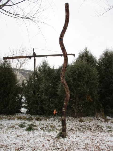
The projects goal is: Replace the pole that supports a Barn Owl nesting box.
The project objectives are: Create a new support pole with a total above ground height of 20 feet, made from 6 inch diameter 10 gauge wall thickness steel pipe, that has the finished shape of a hemihelix with a perversion. The two spiral sections will each be made from a 15 foot piece of pipe and have a finished height of 10 feet each when measured from end to perversion. I want each spiral section to make 2 & 1/2 rotations between end and perversion. The completed pole should resemble an hour glass shape with pointed top and bottom and slender mid section.
The task list describes how to cut 21 pipe segments of 6 differing lengths and with angle end cuts that vary between 8 and 16 degrees. I'll use a proprietary method to accurately adjust the rotation between the angle cuts faces on each end of each piece of pipe. I fear however that erroneous assumptions scurry, like a Mus (Mus), undetected through my proposed script.
The construction process is tedious, but not difficult. Mistakes compound, and are stumbled upon rather than prevented. Field-fit adjustments help but can not overcome the unexpected twists of a best-guess cut list. Any custom fit on one spiral could be difficult to repeat on its mirror spiral.
I find myself griped like a claw, between metal fabrication ability and math/computer skill inability. I am reticent to ask anyone to spend their valuable time on a project that they will neither witness directly nor derive tangible benefit from.
I fear this shape prediction project is screwed between the proverbial Rock-and-a-Hard-Place conundrum.
I can but rely on the kindness of computer savvy strangers.
Thanks, Doug -
Ramani AswathCan you please make a hand sketch, scan and put up here
-
Charles BowerThank you Mr Ramani. I'll try.
Is the "Tinkercard | Create 3D digital designs with online CAD", mentioned by Mr. Italiya a free CAD design tool or does one have to purchase the product in order to use it? -
Harshad Italiya
It's free tool. Also there are other available but never tried.Charles BowerThank you Mr Ramani. I'll try.
Is the "Tinkercard | Create 3D digital designs with online CAD", mentioned by Mr. Italiya a free CAD design tool or does one have to purchase the product in order to use it?
You are reading an archived discussion.
Related Posts
With an Amara Raja Amaron Tribal UPS/Inverter 1400va/24v and with a connected load of 365 watts I need a back up for 4 hours. I have 2X12 V 150ah batteries....
When and how does over heating occurs.....
Is it true that when driving your car with first gear overheating occurs....an How is that possible if so..
Hi...am Kofi an engineering student and an auto mechanically... I just join the forum.....and please forgive me for my late introduction.....
Hi,
I m entc engineer with aggregate 58%. I want to get into it sector. What should do. Batch 2016 pass out.
Adding to its ‘P series’, Gionee has unveiled P7 smartphone in India priced at Rs. 9,999. The device flaunting metal edges features a 5-inch (720 x 1280 pixels) HD IPS...